Please upgrade your browser to the latest version to view our website

East Port Said Seawater Reverse Osmosis Desalination Plant

Introduction

The Egyptian Government awarded the joint venture (JV) comprising Metito and Orascom the East Port Said Seawater Reverse Osmosis (SWRO) Desalination Plant under the Armament Authority of the Egyptian Armed Forces and technical supervision of the Engineering Authority of Egyptian Armed Forces-Water Department. The project is in alignment with Egypt’s water security targets by securing the domestic water requirement for a new urban and industrial area in East Port Said. The 150,000m³/day plant is the primary source of drinking water for almost 1 million residents.

The USD130 million plant is built on 79,000m², including an area designated for future expansions to provide up to 250,000m³/day of clean drinking water. The project site was carefully selected to be in proximity to East Port Said city, which is the key beneficiary of the produced water.

With hard work, commitment, and dedication to the highest level of quality, health, safety, and environmental specifications, the East Port Said SWRO plant completed 5million man hours without a single injury or time lost during the construction of the plant. This was an outcome of regular audits carried out through the series of health, safety, and environment (HSE) training.

Metito’s scope of work for this turnkey project covers the design, supply, installation, commissioning, startup, operation, and maintenance for one year.

The project was commissioned and delivered in 2021. Metito is currently performing the operation and maintenance.

Innovation

The East Port Said SWRO plant is a true testament to Egypt’s progressive and visionary leadership. It is a great example of how the Egyptian Government engages with the private sector in achieving national water security targets and in improving the quality of life for its citizens.

Metito utilized the most suitable selection of processes for the East Port Said plant according to the location parameter including:

  • Using water beak type seawater intake instead of pipes, due to the location’s shallow seabed
  • A unique intake design by implementing Dissolved Air Flotation (DAF) and Ultra Filtration (UF) in pre-treatment to overcome the high turbidity of seawater in East Port Said
  • Pressure exchanger for the most efficient energy recovery
  • A calcite filter for post-treatment is also used for a safer transfer through the network
  • %50 standby power generation system to ensure continued water production in case of a blackout
  • Soil improvement techniques and piling to overcome the low soil-bearing capacity

Sustainability

Through Metito’s sustainability-focused solutions and employing advanced methods to recover energy from reject water (i.e., highly saline concentrated water), the East Port Said plant is designed to use the least amount of energy per cubic meter of produced water. This positively impacts operations and significantly reduces the project’s carbon footprint.

The standard power consumption of a plant per cubic meter of treated water was 5.5Kwh/m3 was reduced to 3.5Kwh/m3. Furthermore, attending to unique environmental measures, a total power saving of 109,500,000Kwh/year was also achieved. The plant minimizes its environmental impact by disposing of the highly concentrated saline water, the waste produced by the desalination process, in an eco-friendly and safe manner through a complex chemical process. The water is treated with specialized acids to equalize the pH level of the reject water and bring its salinity as close as possible to normal seawater, to protect the marine life in the water drainage area.

Metito is a circular economy enabler. Providing access to clean water betters public health and eliminates water-borne infections. This directly supports economic development, which is in line with the UN’s Sustainable Development Goals No. 11 – sustainable cities, and No. 6 – clean water and sanitation.

Agricultural Drainage Treatment, Recycling and Reuse Plant

Introduction

The Egyptian Government introduced a progressive, multi-pronged strategy to safeguard and preserve the nation’s natural resources through a comprehensive water security agenda that focuses on wastewater treatment, recycling and reuse and seawater desalination in coastal areas. This plan is inline with Egypt’s Sustainable Development Plan – Egypt Vision 2030, which focuses on economic, social, and environmental development.

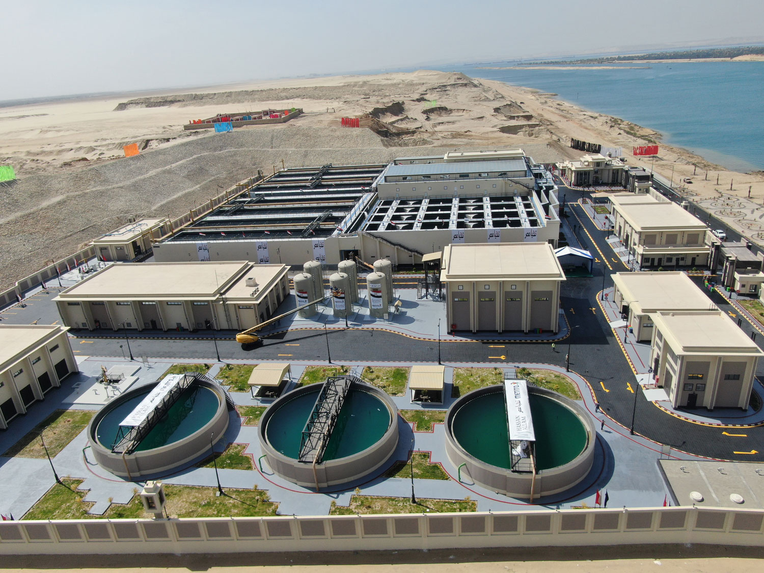
Al Mahsamma project, located in the Ismailia Governorate, is the world’s biggest plant of its type, built over an area of 42,000 square meters with a of 1,000,000m³/day. The plant will contribute to the irrigation of 70,000 acres of land in the Sinai, as part of the government’s efforts to develop the region by creating sustainable urban communities and job opportunities in the area. The plant will also help preserve the natural ecology of the Al Temsah Lake, located west of the Suez Canal, which has been impacted by wastewater disposal throughout the years.

The USD100 million project has been developed by the JV Metito-Hassan Allam, under the supervision of the Armed Forces Engineering Authority. The JV scope of work for this flagship project includes the engineering, construction, operations (EC&O), commissioning and O&M for a period of five years.

Drainage water is transferred to the plant from Ismailia irrigation drainage canal, located west of Suez Canal, through two individual pump stations crossing underneath the Suez Canal (the old and new branches of the canal) into srabuim siphon, from which the water is further pumped through the plant’s pump station using 8 vertical turbine type pumps – six working pumps and two on standby – with each pumping at a speed of 7,000m³/hr.

Al Mahsamma was completed in a record twelve months, amounting to 2.5 million safe man-hours with no injuries or time lost. Latest technologies were utilized for the treatment of drainage water to produce suitable water for irrigation and land reclamation as per the highest quality standards and specs set by the Egyptian Government. Advanced digital and information technology are also being used to monitor the effectiveness of operations and to ensure the quality of water remains compliant with standards and specifications. The project site is equipped with an advanced laboratory for on-site water analysis and quality testing round the clock by dedicated experts.

Scope of Work

The main scope of the JV project included:

  • Engineering and civil design
  • Civil material supply
  • Civil construction
  • Installation of electromechanical equipment
  • Testing and start-up
  • Commissioning on a turnkey basis
  • Operation and maintenance for 5 years

Metito scope covers:

  • Process and electromechanical design
  • Procurement, supply of electromechanical equipment
  • Coordination and supervision of civil works design
  • Intake pump station with 8x7000m3/hr of vertical turbine pump
  • 8 Flocculation tanks, dimensions of each 48.5m length and 8.5 width with 5 gate mixers of each tank
  • 8 Tube settler clarifiers, 1.6m height lamella tubes
  • 28 Disc filters with maximum flow rate 1600m³/hr and 25µ mesh size
  • 3 Gravity sludge thickeners, 19m diameter, and 5m depth
  • Mechanical dewatering stage with 5 belt press, 32.5m horizontal belt conveyor and 7m inclined belt conveyor for sludge

Key Benefits

Environmental Benefits

  • A sustainable project turning wasted drainage – the capacity of 1,000,000m³/day into a valuable source of water for the irrigation of 70,000 acres in dryland area of Sinai Peninsula
  • Making available 1,000,000m³/day for irrigation purposes only by using energy equivalent to 0.1kWh/m³ – result of optimized and efficient design
  • Minimal environmental footprint with effective use of land and making available 1,000,000m³/day for irrigation purposes only by using energy equivalent to 0.1kWh/m³ – result of optimized and efficient design
  • The project will play a role in developing a sustainable community in line with the UN SDGs, creating more job opportunities and encouraging more investment in the area

Challenges

  • Al Mahsamma plant was completed in a record 12 months, compared to the 24-36 months period industry-standard for projects of such scale
  • Due to the strategic location of the plant and proximity to the Suez Canal there were many restrictions and limitations on communication and transportation to and from the site during the development of the project. Moreover, work had to be halted at times, to ensure uninterrupted navigation in the Canal
  • Minimal land was required to be utilized for this project due to the strategic location with required efficient fitting of huge equipment into limited areas

Seawater Reverse Osmosis Desalination Plant

Introduction

In line with the Egyptian government efforts to fortify water resources and reinforce water security, Egypt has witnessed a breakthrough in the development of lifeline water projects. The main objective behind this strategy is to address the low water levels of the Nile River, being the main source of fresh water used in various applications such as: drinking, agriculture, irrigation, industrial, among other potable uses.

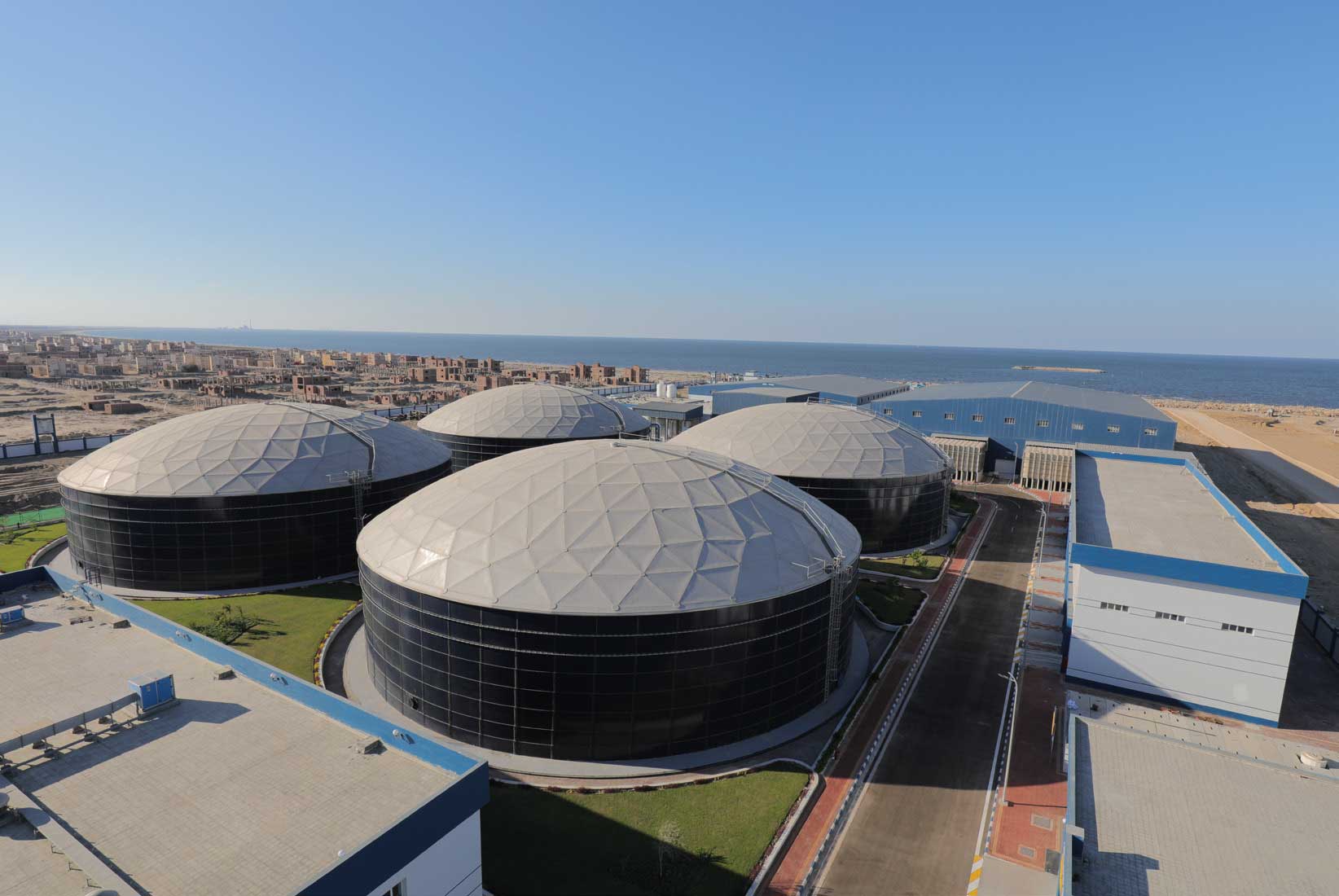
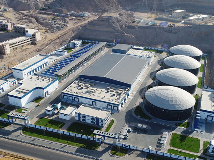
One of the most iconic water projects among this growing portfolio is Al Galala Seawater Reverse Osmosis Desalination Plant (Al Galala SWRO) with a capacity of 150,000m3/day.

Al Galala city is one of the most ambitious projects in Egypt with the vision to become a world-class touristic and residential destination. The entire city is built on 19,000 acres loft land, on top of the highest plateau of Al Galala mountain with a breathtaking view of the Suez Gulf. The city is designed to include world-class hotels, water entertainment parks, an international marina, a commercial and residential complex and a university.

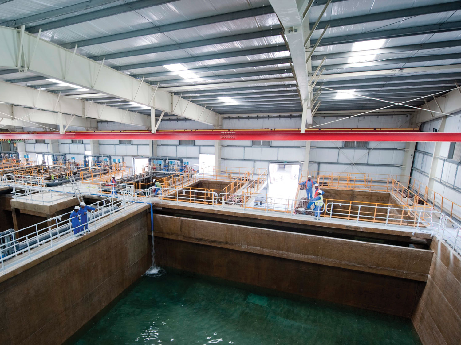
Al Galala SWRO project was developed by Metito, Orascom joint venture (JV), in accordance with the highest standards of quality, health and safety and with a full commitment to preserving the environment. Advanced energy saving technologies have been integrated in this project among which is reverse osmosis. Solid glass-lined steel GLS tanks, providing a wide array of tangible benefits, compared to cement or steel alternatives, have also been used.

Developing Al Galala SWRO was completed in record time despite the obvious challenges that by-factor being located in such an area. The plant is built opposite to a frequent flood site, creating the need to dig tunnels for seawater intake without affecting the main road then lifting desalinated water from coastal level to storage tanks over the mountain. The type of wet soil on which the project is built was also a challenge. However, all such obstacles were overcome and the JV surpassed the set timetable and successfuly commissioned the plant and produced water sixteen months after commencement of construction works. The average industry standards for a project of such size and capacity is thirty months.

Scope of Work

A Turnkey EPC project including operation and maintenance for 1 year.

Main Scope of Work

  • Detailed design and engineering for the entire project including intake, civil works, process, mechanical and electrical work
  • Supply of equipment
  • Marine works
  • Civil works construction
  • Installation, commissioning and startup
  • Onshore and offshore training
  • Supply of spare parts for 1 year
  • Laboratory and workshop
  • Operation and maintenance for 1 year

Scope of Supply

  1. Intake and Outfall
    • Seawater intake 1.6m diameter
    • Seawater intake pumping station
    • Brine outfall pipeline 1.4m diameter
    • Total pipelines length 1,200m
  2. Pre-treatment
    • Horizontal multi-media filters
    • Chemical pre-treatment
    • Micron filtration

    22 Filters 3.8m Diameter 18m length

  3. RO System
    • Desalination reverse osmosis system
    • Energy recovery system (by Isobaric pressure exchangers)
    • RO cleaning and flushing system

    10 RO Skids, 15,000m3 / day each skid

  4. Post-treatment
    • Remineralization system by:
      • Calcite contactors
      • Co2 injection system
      • Degasser with blending tank and pump station
    • Product water GLS tanks 60,000m3 capacity
    • Product water pump station
  5. Electric and Automation
    • Medium voltage switch gear
    • Electric power panels
    • Step down transformers
    • Standby power generators
    • Full automation and SCADA control system

    20,000KVA standby generator set

Key Benefits

  • Design of seawater intake and brine outfall fulfills environmental guidelines to sustain the rich marine life in the area.
  • Reliable design assures a trouble free operation.
  • Integrating a range of software (online hydraulic modelling and leak detection), hardware and services that integrates the concept of “Internet-of-things” and augments reality to monitor the plant’s water and electricity network, ensures a timely and comprehensive on line monitoring of the entire operations, consistent water quality and compliance to international standards and client specifications.
  • Utilizing state of the art technology in energy recovery lowers energy consumption and carbon footprint to minimum level.
  • Equipping the plant with standby generators secures 50% operating capacity for emergency situations and ensuring no downtime.

Demineralization Plant for Trinidad & Tobago Methanol & DiMethyl Ether Project

Introduction

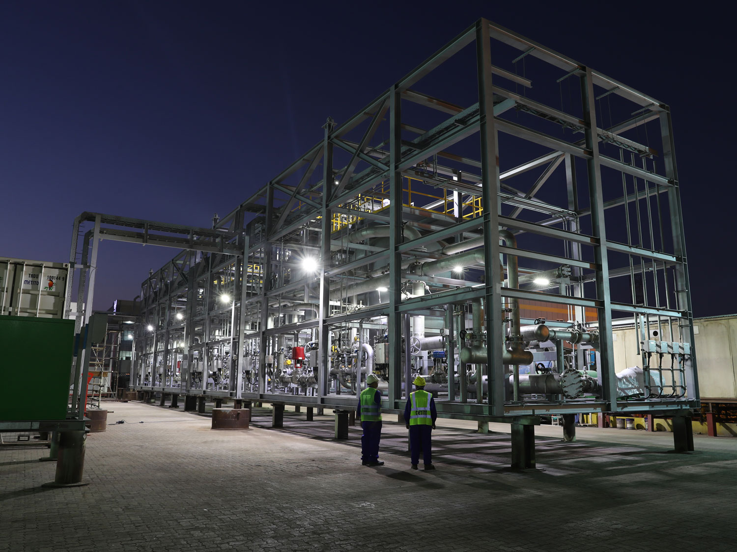
Caribbean Gas Chemical Limited a joint venture enterprise led by the consortium of Mitsubishi Gas Chemical Company Inc., Mitsubishi Corporation and Massy Holdings Ltd., are building a Methanol and Dimethyl Ether plant in Trinidad & Tobago (TMD Project). Mitsubishi Heavy Industries (MHI), Japan were awarded the EPC contract for the project that involved a 200 m3/hr demineralization plant for boiler feed and process requirements. MHI awarded Metito the design and supply of a module-mounted demineralization plant which is a very unique requirement for a plant of this size and for the challenging circumstances due to site location, criticality of skilled manpower and their availability in the region of the project site.

To address this requirement Metito overcame some key challenges: designing and developing such a large capacity module-mounted demineralization plant using minimum module size; ensuring that the module-mounted plant is resilient and able to survive and sustain travelling 8,207 nautical miles through Arabian Sea, Red Sea, and the Mediterranean Sea before its trans-atlantic voyage.

Trinidad & Tobago Dimethyl Ether plant will fulfill the need of Methanol demand in the Caribbean region and beyond, paving way for cleaner and more sustainable energy for generations to come.

Scope of Work

To overcome the challenges presented by this project, Metito proactively minimized site activities by developing a unique module design and incorporating the dynamic packed-bed technology.

Within the scope of work, Metito was responsible for the complete design and engineering, manufacturing, inspection, supply of equipment and materials and delivery to Hamriyah Freeport Zone.

Deliverables included:

  • Demineralization plant – 2x 192 m3/hr consisting of activated carbon filter (ACF) and strong acid cation (SAC)
  • Corrugated plate interceptor (CPI) – 50 m3/hr
  • Cooling water side stream filtration unit – 2 x 131 m3/hr

Module #1

  • Dimensions 21.5m length x 6.75m height x 8.3935m height
  • 4 Demineralization unit feed pumps, capacity 205 m3/hr (each stream) for further treatment
  • 1 Activated carbon filter (piping and cabling)
  • 1 Cation exchanger (piping and cabling)
  • 1 Anion exchanger (piping and cabling)
  • 1 Mixed-bed polisher (piping and cabling)
  • Equipped with all electromechanical accessories

Module #2

  • Dimensions 17m length x 6.75m width x 8.3935m height
  • 1 Activated carbon filter (piping and cabling)
  • 1 Cation exchanger (piping and cabling)
  • 1 Anion exchanger (piping and cabling)
  • 1 Mixed-bed polisher (piping and cabling)
  • Neutralisation piping network
  • Equipped with all electromechanical accessories

Module #3

  • Dimensions 16m length x 6m width x 4.05m
  • 4 Chemical tanks and 8 chemical dosing pumps (piping and cabling)
  • 4 Regeneration pumps (piping and cabling)

Module #4

  • Dimensions 6m length x 3m width x 2.69m height
  • 2 DMW unit wastewater pumps (piping and cabling)
  • 2 DMW unit agitation blowers (piping and cabling)
  • Equipped with all electromechanical accessories

Module #5

  • Complete Vario Frequency Drive (VFD), Programmable Logic Controller (PLC) and Control System housed in a 40′ standard container that controls the total plant.

Key Benefits

  • Complete plant skid-mounted for demineralization unit including the pressure vessels.
  • Asset protection resulting from a completely pre-tested and mock-assembled module at workshop to avoid any mishaps / short supplies at site.
  • Water savings due to the packed-bed technology used for lower chemical consumption and thus lower water requirements.
  • Multitude of environmental benefits due to the modularized plant designed by Metito.

Water & Wastewater Treatment Plants for Asam-Asam Steam Power Plant

Introduction     

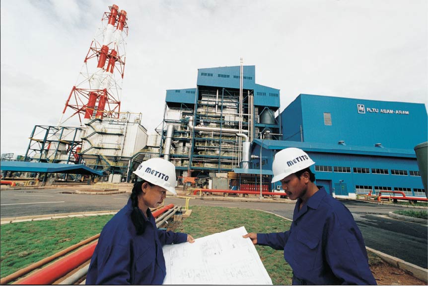
The Indonesian government awarded an international consortium, comprising Sumitomo Corporation and Toshiba Plant Kensetsu, a contract for a 2×65 MW coal-fired power plant for the city of Banjarmasin, located on the island of Kalimantan. This USD 300 million project was financed by the World Bank.

This project was truly unique and undeniable challenging due to many reasons, including: The salinity of the water source/the Asam River during the dry season, with the location being very close to the sea. This proximity causes a wide range of hourly changes in the quality of the raw water with the total dissolved solids varying from 30 to 27,000 mg/l, and the suspended solids varying from 5 to 690 mg/l.

Scope of Work 

  • Metito was responsible for the design and erection of the complete electromechanical works for this package, which comprised of the following treatment plants:
  • River Water Treatment Plant with a capacity of 2×480 m3/h, incorporating solids contact clarification, sludge dewatering system and chemical handling facilities
  • Seawater Reverse Osmosis Plant, constructed in 2 streams
  • Brackish Water Reverse Osmosis Plant with a capacity of 360m3/day
  • Demineralisation Plant for the Packed Bed process, with a capacity of 360 m3/day, comprising 2 streams of cation and anion columns followed by mixed bed polishers
  • Ash and Coal Runoff (ACRO) Wastewater Treatment with a 12 m3/h capacity
  • Metal Cleaning Wastewater Treatment Plant for boilers and air pre-heaters
  • Sanitary Sewage Treatment Plant
  • Skid-mounted cooling water chemical dosing packages
  • Supply of chemicals for the operation of the water and wastewater systems and cooling tower

Key Benefits

  • A total solution for the power plant water and wastewater treatment needs
  • An efficient design that takes into consideration the varying quality of the feed water from seawater to muddy floodwater
  • A novel technology and reliable design that meant trouble-free operation and minimum downtime
  • Timely execution which was imperative for the startup of this power plant
  • Full local support and customer service, in world-class quality, from a well-established company

Saadiyat Sewage Treatment Plant

lntroduction

The Tourism Development and Investment Company(TDIC) is the master developer for key cultural, residential and tourism destinations in Abu Dhabi.TDIC philosophy is based on delivering best practices across every segment in which it operates – be it luxurious resorts, eco tourism or world class cultural hubs.

Just 500 meters off the coast of Abu Dhabi, TDIC is developing Saadiyat Island,a unique place that will offer visitors, housing, cultural, social and entertainment facilities. Leighton Contracting, the main infrastructure development contractor of the island, chose Metito to construct and put into operation new sewage treatment works to serve the Saadiyat cultural district which encompasses Zayed National Museum, Saadiyat Beach, Saadiyat Marina, the Golf Course, an International School, Saadiyat Promenade, Arab World Museum, Saadiyat Lagoons, Saadiyat Retreat and Saadiyat Reserve 5 stars hotel.

In view of the prestigious nature of this development, the membrane bioreactor technology (MBR) was chosen for the project. MBR produces high quality effluent that can be safely used in open irrigation with no health hazard. Treated and disinfected effluent from STW is discharged to an irrigation network to be re-used for landscape irrigation.

Scope of Work

The project was awarded to Metito on design and build basis, that included design, supply, civil construction, installation, commissioning and operation for 1 year.

The sewage treatment plant (STP1) was designed to allow for an increase in capacity to accommodate the rise in occupancy of Saadiyat Island. The plant current average design flow is 11,000 m3/day whilst the maximum design capacity is 16,500 m3/day.

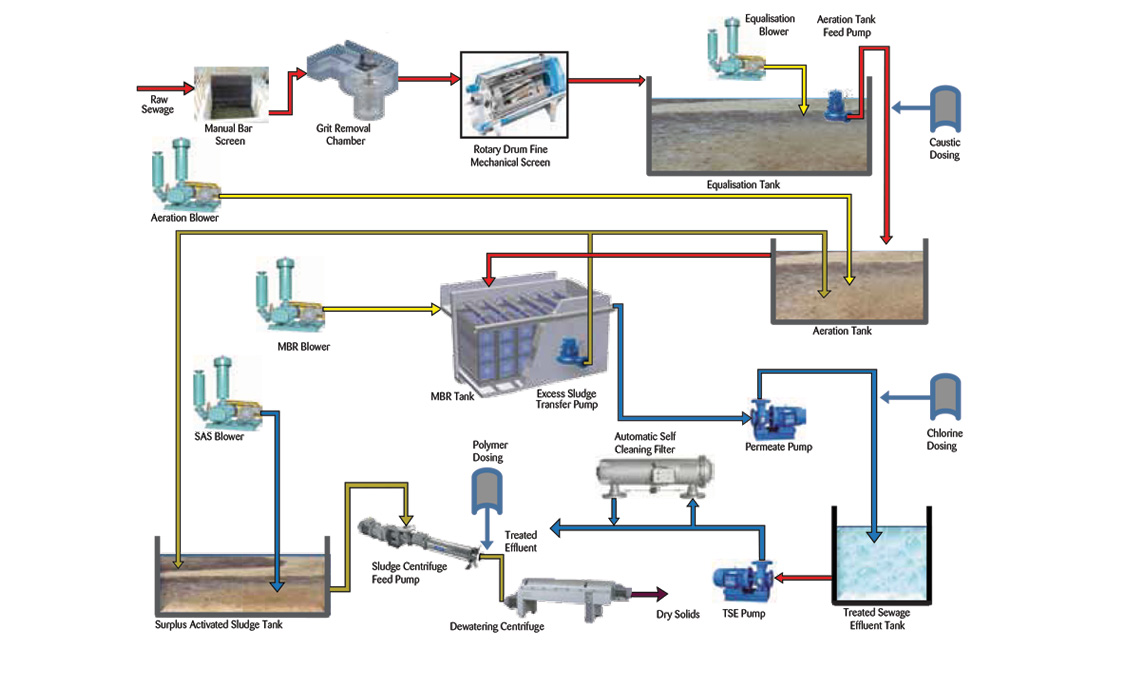
The plant comprises the following key stages:

  • Inlet works
  • Equalisation tank
  • Biological treatment
  • Disinfection
  • Sludge handling
  • Odour control

Process Description

Flow from the pumping stations arrives at a receiving chamber, where it is directed to the inlet works pre-treatment station. The station includes sand, oil and grease removers, a sand classifier, two fine screens (one duty and one stand-by), and one screw compactor for screened material.

Raw sewage from the reception chamber passes through screens to remove all floating material. Screenings are then discharged to a screw conveyor where they are compressed through a compactor and transferred to a receiving skip. The screened material is transported off-site by a registered waste contractor and disposed of to landfill.

Following screening, sewage flows to a vortex type grit chamber where it goes through a rotational flow pattern. The resulting sewage velocity is sufficiently high to prevent the settlement of light organic solids while the heavier sand and grit settle to the bottom of the tank. De-gritted sewage passes through a flow measurement channel to the equalisation tank for further treatment, while collected grit slurry is pumped and delivered to a classifier where water and grit get separated. Water is drained back to the equalisation tank, while solids are transported by conveyor belt to a skip and taken off-site for appropriate disposal.

Flow equalisation overcomes the operational problems caused by varying flow rate patterns, and improves performance of the subsequent processes. Equalisation also  buffers BOD fluctuations and eliminates shock loading.

Air under low pressure is supplied through down feed pipes with diffusers to the bottom of the equalisation tank to prevent settling and septic decomposition of organic matter.

Aeration Tanks

Sewage is pumped by the feed transfer pumps to the aeration tanks. The aeration tanks provide an aerobic environment to ensure nitrification of ammonia and oxidation of BOD,which is achieved by the provision of high efficiency, fine bubble diffused aeration. The aeration tanks include an anoxic zone for effective de-nitrification.

The air blowers are provided with variable frequency drives linked to a Dissolved Oxygen (DO) meter, to maintain the desired residual DO concentration in the aeration tanks.

Two horizontally mounted rotor aerators are provided in each aeration tank, which help mix the activated sludge and increase the amount of oxygen by creating turbulence in the water.

pH Balancing – Sodium Hydroxide

Alkalinity in wastewater results from the presence of hydroxides(OH-),carbonates(CO3-), and bicarbonates (HCO3-). The concentration of alkalinity in wastewater is important where biological nutrient removal is used. Alkalinity is maintained within the required range by injecting sodium hydroxide in the aeration tanks.

Membrane Bio-Reactor (MBR) Tanks

Submerged membrane technology is an advanced cost effective technology. The MBR process is a suspended growth activated sludge one that utilises micro porous membranes for solid and liquid separation in lieu of secondary clarifiers (settling tanks).

There is a total of six membrane tanks which combine the function of solid separation and biological degradation. The membrane units remove solids to < 5 mg/l. They are scoured by coarse bubble aeration to prevent fouling. Provision has been made to chemically clean the membranes, usually twice per year, using dilute Sodium Hypochlorite for bio-fouling. A diffuser flushing system is also used to periodically flush the coarse bubble diffusers.

Surplus sludge is drawn from the membrane tanks at approximately 1.4% to 1.8 % dry solids, and is transferred to a tank.

Disinfection

The MBR process removes a large portion of bacteria from sewage. However, the effluent from the system may contain some pathogens due to contamination. For this reason,  Sodium  Hypochlorite is dosed into a Chlorine
Contact Tank to remove or inactivate the remaining pathogenic bacteria.

After disinfection, TSE from Saadiyat STP-1 is transferred to a treated water tank, and is used for irrigation on Saadiyat Island and as top-up water for Saadiyat Beach Golf Course Lake 15.

Excess sludge from the MBR tanks is pumped intermittently by the sludge recycle pumps to the SAS tank. The tank is provided with an aeration system to prevent the settling of suspended solids. SAS sludge is then transferred by progressive gravity pumps to sludge centrifuges for dewatering, aided by polymer injection.

Dewatered sludge is conveyed via screw conveyors to sludge skips, where it is taken off site by a registered waste contactor for disposal at landfill.

Structures that may generate odour include:

  • Inlet works (channels & chambers)
  • Equalisation tank
  • SAS tank
  • Centrifuges housing

All of these structures will be vented to the atmosphere via an odour control system.

The odour control unit includes two counter-current scrubbers in series, followed by an activated carbon vessel as a deodorising unit (DU). In addition, a second line of counter current scrubbers which are connected to the same activated carbon vessel, are connected together with a stand-by fan.

Hydrogen Sulphide laden air passes through the inlet ductwork and enters the odour control wet chemical scrubber.

Gases move vertically upwards from the low-level side inlet through the packing contained in the tower. A downwards flow of scrubbing liquor intimately mixes with the up-flowing gas resulting in removal of the sulphur based compounds. A conductivity meter monitors the conductivity of the re-circulating liquor.

From the first packed section of the scrubber gases pass to the second packed section where the process is repeated thus providing the final cleaning of foul air. Gases then exit the tower through a mist eliminator. Free drops of water are removed from the gas stream by impact on the chevron collection elements. Collected moisture coalesces into a sheet of liquid that drains freely back into the scrubber vessel.

The activated carbon vessel is used to further reduce the low H2S concentrations after the scrubbers.

The vessel is filled with regenerable activated carbon on which the malodorous organic compounds are adsorbed, and the incoming hydrogen sulphide catalytically oxidised in the fine pore structure of the carbon. The carbon used is vapour phase activated carbon that has been specifically developed for odour removal in sewage treatment operations.

A detection of hydrogen sulphide at the upper air sampling port indicates when the activated carbon has no further adsorption capacity for hydrogen sulphide, at which time it is regenerated.

The odour control installation is designed to the following standards:

Flow Rate 10.000m3/hour
Maximum H2S inlet concentration under natural ventilation 500
Mean H2S inlet concentration under natural ventilation 200 ppm
Air Temperature Ambient
Maximum H2S outlet concentration 0.00047 ppm

The STP is designed to treat domestic sewage. The influent characteristics are summarised in below table:

No. Parameter Unit Value
1 Flow (Average) m³/d 11000
2 Peak Flow Daily m³/h 458.3
3 Pumping Hours Hours/d 24
4 pH 7.5
5 TSS mg /l 270
6 BOD5 mg /l 290
7 COD mg /l 590
8 NH4-N mg /l 30
9 TKN-N mg /l 40

The project had a prerequisite requirement that necessitated the execution of an environmental impact assessment study before commissioning of the sewage treatment works. To accommodate this requirement, an Operation Environmental Management Plan(OEMP) was prepared to ensure that the operational activities of the Saadiyat STP-1 are managed in such a way that minimises the risks associated with land, water and air pollution, all in accordance with the requirementsoutlined in Federal Law No. 24 of 1999 for the Protection and Development of the Environment, and the Abu Dhabi Emirate Environment, Health and Safety Management System (EHSMS) Regulatory Framework (Decree42 of 2009).

Saadiyat Island is a bare land that is not connected to Abu Dhabi main sewage drainage system. This STP plant treats sewage generated on the island and the treated water is then used for irrigation purposes to maintain the green environment in the island. The need to construct a pipeline connection to the nearest sewage mains and additional pumping stations are eliminated, thus minimising the investments/financial exposure required.

Process Schematic Diagram

Sewage Treatment Plant

Introduction

The existing sewage treatment plant at The Greens residential community in the emirate of Dubai was subject to a major increase in sewerage flow due to a rapid increase in population. There was therefore a need to augment the plant treatment capacity in the shortest possible time to meet the additional load. The job of augmentation however was fraught with many constraints such as:

  • Lack of sufficient space for expansion
  • The physical limits of a high traffic road at the southern boundary, a school at the eastern side and some infrastructure at the northern and western ends. These limitations presented major challenges in accommodating the plant within the small available footprint and catering for both odor control and aesthetic view of the structures
  • The difficult task of integrating the new plant into the existing one without stopping the inflow. which could not be diverted elsewhere
  • Incorporating the new equipment into the existing STP structures

Metito took up the challenge and proposed a solution using MBR (Membrane Bioreactor) technology that was a nascent new process in the Arabian Gulf region.

Metito was awarded the multi-million dollar utilities project to increase the treatment capacity of the existing sewage treatment plant at The Greens from 3,000 m3/day to 10,000 m3/day, by employing Membrane Bioreactor technology. The process scheme was developed to make the best possible use of the existing treatment plant structures and add minimal new ones. Project execution involved complying with the international standards and specifications drawn by the consultants. Metito completed this most challenging task to the entire satisfaction of the owner, and the successful operation of this entire complex was subsequently managed by Metito’s efficient and professional workforce.

Scope of Work

This included detailed engineering, manufacture, supply, installation, testing, commissioning, start-up and training of personnel at the site. It also included the operation and maintenance of the plant for a period of three years.

Plant General Information   

The sewage treatment facility comprises the following units:

  • Inlet works
  • Biological Treatment
  • Sludge Handling
  • Chemical Cleaning
  • Electrical and Control System

Plant Technical Characteristics

Raw sewage from the residential community is transferred by a force main then screened before entering the main sewage lift station.

Plant Data Summary

Average daily flow 10,000 m3/day
Peak daily design flow 12,000 m3/day
Peak factor 2.5
Peak hourly flow 1,042 m3/hr
Peak flow duration 2 hours

Influent Analysis                  

Parameter Unit Value
Temperature C0 22-35
BOD5 mg/l 300
COD mg/l 700
TKN – N mg/l 50
NH3 – N mg/l 40
Suspended Solids mg/l 325
Phosphates mg/l 10
Alkalinity (Assumed) mg/l Min.250
Oil & Grease (Assumed) mg/l < 25
Ph mg/l 7 – 8.5
Sulphate mg/l 90
Hydrogen Sulphide mg/l 27

Effluent Quality

Parameter Unit Value
Temperature C0 22-35
BOD5 mg/l < 10
COD mg/l < 50
TKN – N mg/l < 5
NH3 – N mg/l < 3
Suspended Solids mg/l < 10
Total N mg/l < 30
Total coliform mg/l < 10c/100 ml

Process Description

Metered raw sewage from the mains is released into a concrete channel through two 25mm perforated plate coarse screens operating on a duty/standby basis, then through two 3mm perforated plate fine screens also operating on a duly/standby basis. The inclined screen basket separates floating and suspended materials from the wastewater. The screen surface is cleaned by spray nozzles as the basket is rotating. For clean and easy handling, the collected waste from the screens is compacted and dewatered up to 40% w/w. A Vortex-type grit removal system with a grit classifier is installed after the screens to remove heavy grit particles.

Partially treated raw sewage enters the newly constructed lifting station, from where it is pumped to the existing balancing tank. The tank contents are constantly mixed by submerged mixers to maintain the sewage in the agitation and prevent it from turning septic.

Downstream membrane treatment is divided into three process trains to cater for plant turndown and to provide flexibility in operation. The biological treatment of each process train comprises the following process units

The existing STP had two primary settling tanks. One of the existing settling tanks was converted into an anoxic tank and the other into an equalization/balancing tank. The anoxic tank receives partially pre-treated equalized sewage that has been intimately mixed with nitrate-laden recycled flow from the membrane tanks. Soluble and particulate COD in the incoming sewages utilized by bacteria to effect de-nitrification under anoxic conditions. Submerged mixers in each anoxic tank keep the bacteria in suspension, homogenously mixed with the soluble nitrate.

Sewage from the anoxic tanks passes to the aeration tanks by gravity. The existing tanks were maintained for this purpose and surface aerator were replaced by fine bubble type diffused aeration. The aeration tanks provide an aerobic environment to ensure nitrification of ammonia and oxidation of BOD. Air supply to the diffuser system is monitored and controlled automatically to maintain optimum residual dissolved oxygen (DO) concentration in the tanks.

Three membrane bioreactor tanks serve the function of solids separation whilst also assisting in the provision of air for the biological degradation processes. Each membrane tank contains 14 membrane units arranged in a double-deck configuration. To prevent surface fouling, membranes are continuously scoured by air supplied through diffusers placed below the membrane blocks. Provisions were made to chemically clean the membranes, if and when required. A diffuser flushing system is used to periodically flux the coarse bubble diffusers. Flux rate control is a critical operational feature, hence flow through the membranes is controlled by modulating the permeate control valve to achieve the required flow rate.

The recycle rate is fixed at three times the average flow. The recycle pumps are designed for intermittent operation to ensure a maximum recycle rate in low flow conditions. Intermitten to operation is set according to the pre-determined schedule controlled by a PLC.

The main treatment process removes a wide spectrum of bacteria from the sewage. Chlorination using sodium hypochlorite is however imparted in to permeate streams to remove or inactivate any pathogenic bacteria that may grow in the final storage tanks.

Biological sludge is pumped to the sludge digesters. Sludge is digested and stabilized under aerobic conditions. Digested sludge is then pumped to a dewatering centrifuge to produce 20 – 25% dry sludge. Concentrate from the centrifuge is returned to the plant inlet for recovery.

This includes a state-of-the-art SCADA system, PLC control panels, MCC’s, cabling, wiring, earthing, and plant lighting. Power to the STP plant is fed from a facility substation equipped with dual incomers (mains supply from DEWA as well as emergency supply from a fixed generator). The plant is completely powered, monitored, and controlled from the STP control room. The design of the control equipment allows for separate and independent operation of the MBR streams, so that failures in the control equipment associated with one stream will result in the shut down of the affected stream only. This is achieved by efficient utilization of PLC I/O’s. Important factors such as availability of plant, efficient use of manpower, high reliability and simplicity of maintenance have been considered in the design. The control system has been designed for full automatic operation with minimal observation from operator. Important process variables are logged in SCADA and can be viewed as historical/real-time trends to review the performance of the plant.

The plant provided the advantage of minimum footprint and maximum utilization of existing structures whilst maintaining the overall architectural and aesthetic requirements. Technically it utilizes a modern up-to-date process that ensures a consistent quality of treated effluent.

Seawater Desalination Plant

Introduction

Port Ghalib, a world class resort located along the southern Red Sea coast, at Marsa Alam in Egypt. This integrated development spans 18 km of pristine beachfront, with access to the Red Sea turquoise blue waters and world famous coral. The Resort is recognised as a model for environmental conservation, cultural preservation, design creativity, beauty and diversity of entertainment and leisure experiences.

Due to Port Ghalib’s location, it was necessary to create an infrastructure to supply water, power and waste treatment needs for the area. Consequently, the water desalination plant, one of the major utility design and construction contracts for Port Ghalib, was awarded to Metito.

Scope of Work                                                                                                 

Metito was assigned with the turnkey design and construction of the complete civil-electromechanical work for the plant. This included;

  • Beach well intake pumps
  • Raw water storage tanks
  • Raw water disinfection system
  • Polyelectrolyte injection for coagulation
  • Automatic dual media pressure filters
  • Dechlorination agent injection system
  • Acid & Antiscalant injection systems
  • Micron cartridge filters for membranes protection
  • Multistage Duplex SS high pressure pumps with energy recovery turbines
  • Seawater membrane racks:
    • 2×500 m3/day plus 2×1000 m3/day for phase I
    • 3×1000 m3/day for phase II
  • Lime injection systems for pH correction
  • Hypochlorite injection systems for post-chlorination
  • Membrane flushing and cleaning system
  • Product water tanks
  • Product water transfer pumps
  • Electrical substation & transformers, HV & LV MCCs
  • Distributed control system

Key Benefits                                                                                                     

  • A total solution for the water needs of the resort
  • An efficient design that takes into consideration the stringent requirements set by the owner and the project manager
  • An ‘’Environmentally Friendly” plant that has minimum effect on the surrounding marine life and coral formations
  • Well proven technology and reliable design that meant trouble free operation and minimum downtime time
  • Lower energy usage due to the utilization of specific environmentally friendly equipment, which results in a lower carbon footprint
  • Full local support and customer service, in a world-class quality, from a well established company

Seawater Desalination Plant

Introduction

The Pearl Qatar is an iconic and innovative mixed-use urban development in Doha, Qatar. The Pearl is owned and developed by United Development Company (UDC), a Qatari shareholding company with a mission to identify and invest in long-term projects contributing to Qatar’s growth. The island spans over four million square-meters of land that was meticulously developed into a masterpiece of private and modern living. The Pearl offers residents and visitors a complete lifestyle experience that includes residential units built to the highest international standards, a fantastic choice of retail, dining and hospitality outlets and a host of other amenities and facilities.

The Pearl’s first phase and gateway to the island also houses the world’s longest waterfront luxury retail walkway, the 3.5km marina-front pedestrian boardwalk called ‘La Croisette’. UDC awarded Metito the project to construct a Seawater Reverse Osmosis (SWRO) desalination plant to supply water for potable purposes, district cooling and irrigation with a flow capacity of 40,000 m3/day.

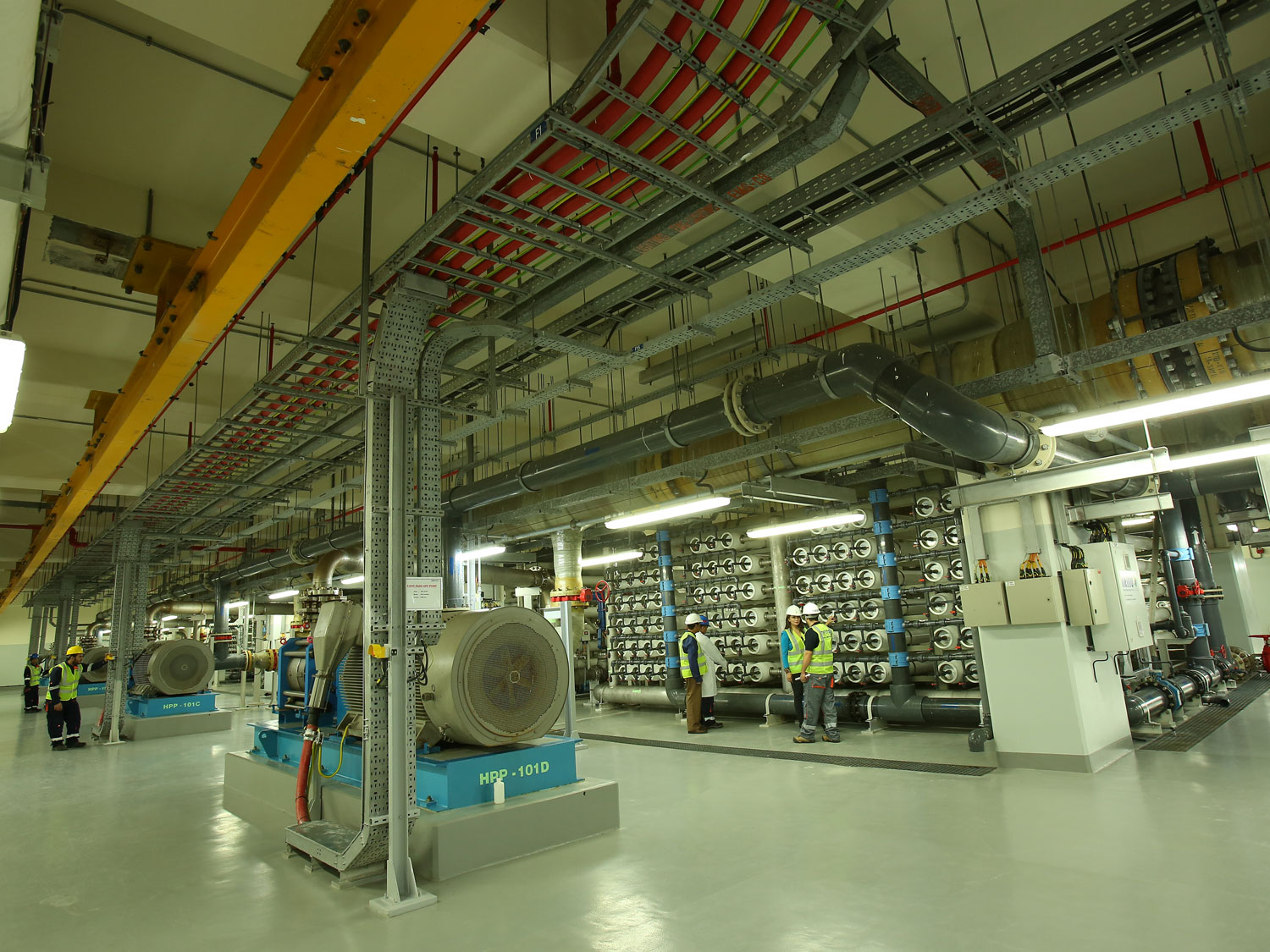
Due to the reclaimed nature of the land and its prime value, it was not permitted to construct a plant with conventional horizontal layout and this constituted a major challenge. To overcome this challenge, Metito adopted an effective, sustainable and practical solution; building a multi story structure comprising 4 levels:

  • Basement floor: This stands at below seawater level where the filter feed pumps, pressure filters, product water pumps, irrigation transfer pumps, filter backwash pumps and air scouring blowers, are all housed
  • Ground floor: Home to the cartridge filters, chemical conditioning systems, and carbon dioxide storage and injection system
  • Mezzanine Floor: Houses the MCCs and LV systems
  • First floor: This houses the high pressure pumps for 1st and 2nd passes, energy recovery turbochargers, 1st and 2nd pass membrane racks, control systems and 3.3 KV HV MCC for the huge 1st pass high pressure pumps

Another challenge was ensuring the treated water permeate salinity is less than 400ppm, in compliance with the local water quality standards. To overcome this challenge, Metito utilised the 2 pass RO system.

Scope of Work

The scope of work included design, engineering supply, installation and commissioning, and operation of the SWRO plant which required the following:

  • Two travelling band screens for seawater intake
  • Chemical conditioning for disinfection and coagulant dosing
  • Six filtration forwarding pumps to feed the disinfected water to the pressure sand filters
  • A total of 15 horizontal multimedia pressure sand filters to separate fine suspended particles and colloidal particles
  • Pre-treatment through antiscalant and dechlorination agent dosing
  • First pass SWRO plant and second pass Brackish Water Reverse Osmosis plant
  • Post-treatment using chlorine, lime and CO2 injection
  • Brine outfall pipeline
  • Installation of two concrete seawater intake heads including coarse sea level

Key Benefits

Financial Benefits

  • An efficient design that takes into consideration the stringent requirements laid down by the owner and the consultant, and that saves on the cost of prime land that would have been alternatively required to build a horizontal plant instead of multi story structure

Environmental Benefits

  • Practical measures have been taken to preserve marine life and the surrounding environment after conducting an Environmental Impact Assessment study to assess the area affected by the construction and operation of the plant, and thereby develop the required measures to minimize environmental impacts
  • The technologies used reduce the eco footprint of the plant as they are integrated using low carbon emission equipment such as turbo chargers which are able to recover energy from brine

Wastewater Treatment Plant for Ruwais Housing Complex

Introduction  

The town of Ruwais lies 250km west of Abu Dhabi, the capital of UAE where the largest oil well fields and petrochemical industrial complex are located.

The successful operation of this entire complex is managed by Abu Dhabi National Oil Company’s (ADNOC) professional and dedicated workforce. ADNOC has constructed a township providing the most modern amenities for all its employees and other associated companies. The township is named Ruwais Housing Complex.

ADNOC plans for continued growth necessitated the expansion of the present township. While conforming to its commitment to maintain the highest standards of environmental protection, and its augmentation of the township’s infrastructure was part of this planned work. This included expansion of the drinking water supply and a modern wastewater treatment plant.

Metito was awarded the multi-million US Dollar utilities expansion project against tough competitive bidding. Project execution involved complying with the international standards, as well as the specifications drawn by ADNOC and its consultants CRSS International. Metito successfully completed this most challenging task to the entire satisfaction of the project owners.

Scope of Work 

This included the detailed engineering, manufacture, inspection, supply, installation, testing and commissioning, start-up, performance test and training of personnel at site.

Plant General Information                                                        

The drinking water and wastewater treatment facilities are extensive and mainly comprise the following units:

  • Drinking water treatment, storage and pumping
  • Sewage pumping stations
  • Sewage treatment plant
  • Sludge digestion & handling facilities
  • Irrigation pump station
  • Electrical and control equipment
  • SCADA System
  • Miscellaneous site works

Plant Technical Characteristics

Drinking water from the main water supply line is stored in two 20,000 US gallons capacity storage tanks. A fully automatic chlorination system renders water suitable for drinking purposes. The disinfected water is delivered to the housing complex through a set of transfer pumps. The minimum water supply pressure is maintained through the use of two 129m3 hydro-pneumatic tanks. The tanks are in carbon steel construction and designed as ASME (U) STAMPED pressure vessels. All associated compressors, controls and monitoring devices are designed for fully automatic operation.

Raw sewage from the housing complex is transferred to a main sewage lift station through two intermediate pumping stations from the plant located at distances of about three and five kilometers. Each intermediate pumping station is provided with two sewage lifting pumps, each having a capacity of up to 100 m3/h. From the main sewage lift station. sewage is pumped to the wastewater treatment plant. Four pumps transfer the sewage to the treatment site. The pump capacities vary from 260m3/h to 560m3/h. The lift station equipment is installed about 11 m below ground, and the dry well is furnished with advanced ventilation and odour control equipment.

This includes the following units:

  • Raw sewage metering station
  • Inlet headworks
  • Aeration tanks
  • Clarifiers
  • Secondary coagulation, flocculation and settlement
  • Travelling bridge gravity filters
  • Sludge digestion and handling
  • Gas chlorinating equipment
  • Effluent pumping station
  • Irrigation pumping station

The inlet headworks comprise grit removal and disposal facilities to remove the heavy grit particles, followed by automatic and manual screens that remove large floating and suspended objects from raw sewage.

Partially treated raw sewage enters two circular aeration tanks 44m in diameter. To achieve economy, the tanks are constructed as earthen basins with waterproof liners. The integrity of the liners is continuously monitored through a uniquely designed leak detection grid installed under each liner. Each aeration tank is combined with an anoxic zone for effective de-nitrification. Two 75kW Brush Rotors are installed in each basin to meet the aeration requirements.

The aerated sewage passes through two circular clarifiers 13.5m in diameter. The effluent flows through a peripheral inlet and central collection system, and the clarifiers are equipped with gear-driven central cage and rake mechanism. Sludge is raked into a central cone at the bottom of the clarifier. The pipework is arranged to provide continuous sludge re-circulation and excess sludge discharge.

Biologically stabilised treated waste is further treated by a coagulation and flocculation process, and fine suspended solids are again removed by the sedimentation process with the help of two 5Om x 5Om x 4.5m deep settlement tanks. Like the aeration tanks, these tanks are also designed as earthen basins with waterproof liners and continuous monitoring leak detection.

Clarified water is treated in the gravity filters to further improve the quality of water. The filters are provided with traveling bridge backwash equipment mounted on a frame structure that moves along the filter via a mechanism powered by a reversing motor. The backwash equipment. comprising a moving stainless steel hood and the submersible pump is mounted on this bridge. Hydraulically sized orifices are provided to collect the backwash water  uniformly.

Sludge from the biological and clarifier stages is pumped to two 1,150 m3 digester tanks, where it is digested and stabilised under aerobic conditions. Two centrifugal air blowers, each having a capacity of 3,300 m3/hr, supply the required air. Digested sludge is pumped to a circular sludge thickener 15m in diameter, from which thickened sludge is pumped to the sludge drying beds. Underflow from the sludge drying beds and supernatant water from the sludge thickener is returned to the inlet headworks for recovery.”

The complete chlorination equipment is housed in a separate building. Two wall-mounted, vacuum-operated, solution feed, sonic flow type gas chlorinators are supplied to provide chlorine solution to the chlorine contact tank and filters. An automatic switchover facility ensures the continuous supply of chlorine, and the gas feed flow is controlled automatically. Ancillary equipment installed include an on-line chlorine analyzer, chlorine leak detection and gas monitoring and chlorine emergency kit.

The irrigation reservoir receives treated water from the wastewater treatment plant for storage and distribution. The reservoir is provided with inlet control valves and four sets of pumps to supply water to the irrigation system. The water passes through online automatic self-cleaning filters and a hydro-pneumatic tank to maintain minimum pressure in the system.

These include state of the art SCADA, process control panels, MCC’s, cabling, wiring, earthing, plant and street lighting and lightening protection. An ATS/MTS with bypass facility is provided to avoid parallel operation of main and generator incomers to the MCC in line with the latest Water and Electricity Department (WED) requirements. PLC based control panels are located near the individual plant facilities. These are water supply system and other facilities. All control stations are connected to the SCADA system over a multi drop communication link. The SCADA system operates on a dedicated digital leased line to provide continuous information. Drinking water is received from Ruwais refinery located 25km away, and the SCADA system transmits the necessary information to the refinery for an assured supply of drinking water to the housing complex. The link between the two locations is maintained by a fiber optic communication network.

The entire water treatment package was successfully commissioned and put into operation to the full satisfaction of ADNOC. The project is a clear demonstration of Metito’s commitment to provide its clients with the most advanced treatment technologies whilst meeting the most stringent international and local standards.